Chunxin's Blog
Home

Blog

Blog

  • Ball Screw Selection Guide Feb 28, 2025
    Ball screw is an efficient transmission element that converts rotary motion into linear motion. It is widely used in CNC machine tools, automation equipment, precision instruments and other fields. Correct selection is essential to ensure equipment performance and extend service life. This article will introduce the key steps and precautions for ball screw selection in detail.   1. Determine the load conditions 1.1 Axial load Axial load is the primary consideration for ball screw selection. It is necessary to calculate the maximum axial force applied to the screw during operation. The calculation formula for axial load is:   1.2 Radial load and bending moment In some applications, ball screws may be subjected to radial loads or bending moments. These loads affect the life and accuracy of the screw, so comprehensive considerations are required when selecting.   2. Determine the stroke and speed 2.1 Stroke The stroke refers to the maximum distance the ball screw needs to move. Determine the stroke according to the range of motion of the equipment and ensure that the length of the selected screw meets the requirements.   2.2 Speed Speed ​​includes maximum moving speed and acceleration. According to the working requirements of the equipment, calculate the required moving speed and acceleration to ensure that the lead and speed of the selected screw can meet the speed requirements.   3. Select the lead and accuracy 3.1 Lead The lead refers to the distance the nut moves for each turn of the screw. The choice of lead directly affects the moving speed and resolution. The larger the lead, the faster the moving speed, but the lower the resolution; the smaller the lead, the higher the resolution, but the slower the moving speed.   3.2 Accuracy Accuracy is an important performance indicator of ball screws, including positioning accuracy and repeat positioning accuracy. According to the accuracy requirements of the equipment, select the appropriate accuracy grade. Common accuracy grades are C0, C1, C2, C3, C5, C7, C10, etc. The smaller the number, the higher the accuracy.   4. Determine the screw diameter and length 4.1 Screw diameter The selection of screw diameter is mainly based on axial load and speed. The larger the diameter, the stronger the load-bearing capacity, but the weight and cost are also higher. Select the appropriate diameter according to the load and speed requirements.   4.2 Screw length The selection of screw length needs to consider the stroke and installation space. Too long length may cause deflection, affecting accuracy and life, so it is necessary to select the appropriate length according to the actual situation.   5. Select nut type The nut types of ball screws include single nut and double nut. Single nut has a simple structure and low cost, but small preload; double nut has large preload and good rigidity, which is suitable for occasions with high precision and high rigidity requirements.   6. Consider lubrication and sealing 6.1 Lubrication Good lubrication can reduce friction and extend the life of the screw. Select the appropriate lubrication method according to the use environment, such as grease lubrication or oil lubrication.   6.2 Sealing The sealing device can prevent dust and impurities from entering the screw and affecting accuracy and life. Select the appropriate sealing method according to the use environment, such as dust ring or sealing ring.         Conclusion The selection of ball screw is a complex process, which requires comprehensive consideration of multiple factors such as load, speed, accuracy, life, etc. Through scientific selection methods, it can ensure that the ball screw performs best in the equipment, prolongs the service life, and improves the reliability of the equipment. We hope this article can provide valuable reference for your ball screw selection. If you have any needs, please contact us for more information.
  • Development trend of linear guides
    Development trend of linear guides Apr 11, 2025
    As a key component of precision linear motion systems, the development of linear guides in the next three years will be closely centered around high-end manufacturing upgrades, the explosion of intelligent demand, and the deepening of industry applications. Nanjing Chunxin has begun to develop linear guide products linked to intelligence. The following is a detailed analysis of the core development trends: 1. Technology upgrade direction (1) Ultra-high precision and rigidity Nano-level repeatability: The demand for semiconductor equipment (such as photolithography machines) and optical inspection instruments drives the guide rail accuracy to ±0.1μm, which is achieved by optimizing the raceway grinding process and preload adaptive adjustment. Heavy-duty high-rigidity design: Heavy-duty fields such as wind turbine blade processing require guide rails with a static stiffness of more than 500 N/μm, using a multi-slider parallel structure and enhanced roller design. (2) High speed and low friction Speed ​​exceeds 5 m/s (such as packaging machinery), relying on ceramic balls and self-lubricating coatings (such as PTFE composite film) technology, and the friction coefficient is reduced to below 0.001. (3) Intelligent integration Built-in sensor rails: real-time monitoring of load, vibration, temperature, and feedback of wear status through edge computing (such as THK's "Smart Rails"). Self-adjusting system: AI algorithm dynamically adjusts preload and compensates for thermal deformation (especially suitable for high-precision machine tools).   2. Innovation in materials and manufacturing processes Lightweight materials: aluminum alloy rail skeleton (30% weight reduction) + ceramic balls, used in scenarios such as drone servos. Corrosion-resistant special steel: molybdenum-containing stainless steel or surface nitriding treatment is used in ships and chemical environments, and the life span is increased by 3 times. Additive manufacturing applications: 3D printing of complex rail end caps, integrated oil circuits and sensor slots (such as Siemens' directed energy deposition technology).   3. Industry application explosion point New energy field: power battery module stacking equipment: requires rails to be dustproof (IP67) + high speed (2m/s) + long life (10 years maintenance-free). Photovoltaic silicon wafer cutting machine: The demand for dust-resistant rails has surged, and the market size may exceed US$800 million in 2025. Semiconductor and panel manufacturing: Vacuum environment rails (no outgassing materials) are used for wafer handling robots, and global demand is expected to grow by 25% in 2026. Medical robots: Micro rails (width ≤ 15mm) are used for surgical robotic arms and must meet MRI compatibility (non-magnetic materials such as titanium alloys).   4. Market competition pattern Domestic substitution is accelerating: Chinese manufacturers (such as Guangdong Kate, Nanjing Technology, and Nanjing Chunxin) will increase their market share in small and medium-sized rails from 35% in 2023 to 50% in 2026, but the high-end market is still dominated by HIWIN and THK. Cost competition strategy: Large-scale production reduces the price of mid-range products by 10%-15%. Modular design (such as integrated guide rails and drive motor kits) reduces customer assembly costs.   5. Integration of emerging technologies Digital twin operation and maintenance: Build a life prediction model through rail operation data to reduce unplanned downtime by more than 50%.   6. Summary and suggestions The core competitiveness of linear guides in the next three years will be reflected in: Scenario-based innovation (such as explosion-proof guides for lithium battery workshops and clean guides for biological laboratories). Intelligent penetration (upgrade from a single moving part to a "perception-decision" terminal). Industry chain collaboration (co-building an ecosystem with servo motor and controller manufacturers).   If you are looking for high - quality products, welcome to visit our website at www.chunxinauto.com to learn more product information. We look forward to cooperating with you to jointly unlock a new chapter of creativity.   If you are interested in this article, you can contact us at WhatsApp or WeChat +86 17372250019
  • Do you know the uses of linear guides?
    Do you know the uses of linear guides? Aug 28, 2025
    Linear guides have a wide range of applications. They are the "backbone" and "blood vessels" of modern industrial equipment and precision machinery. Their core mission is to provide high-precision, high-rigidity, and high-efficiency linear motion.   I. Core Application Areas 1. CNC Machine Tools - The "Main Field" This is the most classic and important application area for linear guides. They directly determine the machining accuracy and speed of machine tools. Purpose: Controls the movement of key components such as the turret, spindle, and worktable. Specific Equipment: Machining centers, CNC milling machines, lathes, grinders, EDM machines, etc. Function: Enables precise positioning and rapid movement of tools or workpieces in the X, Y, and Z axes, completing the cutting of complex parts.   2. Industrial Robots - "Flexible Joints" Purpose: Serves as the robot's seventh axis (ground rail), extending the robot's travel distance and operating range. Used in linear motion joints within robot arms, they enable precise and smooth extension and retraction. Function: Provides reliable basic linear motion for robots, widely used in robotic workstations for handling, welding, painting, assembly, and other tasks.   3. Electronics and Semiconductor Manufacturing Equipment - "King of Precision"   Purpose: Positioning and moving precision components such as chips, wafers, and circuit boards.   Specific Equipment: Semiconductor lithography machines, chip packaging machines, surface mount (SMT) machines, wire bonders, wafer probers, and LCD panel handling equipment.   Function: Achieving ultra-high-speed, ultra-precision positioning at the micron and even nanometer scales is crucial for the production of chips and electronic components.   4. Precision Measuring Instruments - "Fiery Eyes"   Purpose: Moving sensors or probes to scan and measure workpieces.   Specific Equipment: Coordinate Measuring Machines (CMMs), Image Measuring Machines, and Laser Scanners.   Function: Providing an extremely stable and precise reference motion track for the measuring head. Any slightest wobble will directly affect the measurement results, thus requiring the highest precision from linear guides.   5. Medical Equipment - "Lifeguards"   Purpose: Moving diagnostic or therapeutic components. Specific equipment: CT machines, MRI scanners, linear accelerators (radiotherapy equipment), surgical robots, and automated biochemical analyzers. Purpose: Achieve precise patient movement or precise positioning of treatment equipment, requiring smooth, quiet, and reliable operation.   II. Other Common Applications Automated production lines: Linear motion units in material handling, automated assembly lines, and logistics sorting systems. Laser processing equipment: Guides the movement of laser heads in laser cutting and laser welding machines. Printing equipment: Reciprocating motion of print heads in digital printers and large-format printers. Aerospace: Used as simulation test platforms for components such as aircraft wings and missile servos. Everyday items: Even high-end office furniture (such as height-adjustable desks) and smart home devices can be found in them.   To summarize its core applications: Its ultimate purpose is to ensure that a component on a device is fast, stable, accurate, and able to withstand loads. If you are interested in linear guides, please leave your information and I will contact you in time.
  • Are linear guides prone to rust? Corrosion-resistant and water-resistant! Oct 21, 2025
    Ordinary linear guides often rust in humid environments, affecting their operation. This article introduces a new corrosion-resistant and "water-proof" guide rail solution to protect high-humidity workshops such as cleaning and aquaculture. Hidden dangers of humid environments - the humidity in cleaning equipment and aquatic product processing workshops exceeds 75%, and they are often exposed to coolants and water. Ordinary guide rails will rust within 1 month, and the rust will cause the slider to jam. Maintenance requires rust removal and replacement of accessories, resulting in high monthly maintenance costs.   The guide rails are made of 304 stainless steel (highly corrosion-resistant) with a multi-layer chrome-plated anti-rust coating. They have passed the salt spray test (500 hours) and show no signs of rust. Even with long-term contact with water and coolant, they can remain smooth and rust-free, making them suitable for humid and water-prone environments.   If you have any needs, leave a message and send me a private message to obtain the corrosion-resistant linear guide sample book. Engineers recommend materials based on ambient humidity and contact liquid type!
  • How to install linear guides?
    How to install linear guides? Oct 31, 2025
    Pre-installation Preparation 1. Tools and Materials Mounting Platform/Equipment Base: A pre-machined mounting surface. Hex Wrench: Matches the guide rail bolts; preferably with torque display. Dial Indicator/Dial Marker: With magnetic base for precision measurement. Level: Precision grade; for initial leveling. Marble Platform or Precision Straightedge: As a straightness reference. Lin-free Cloth, High-purity Alcohol, or Acetone: For cleaning. Gloves: To prevent sweat from corroding the guide rails. Screwdriver or Pry Bar: For moving the slide.   2. Cleaning Procedure Clean Mounting Surfaces: Thoroughly wipe the guide rail mounting surfaces, threaded holes, and positioning reference surfaces on the equipment base with a lint-free cloth dampened with alcohol or acetone. Ensure there is no oil, dust, burrs, or old sealant residue. Clean Guide Rails: Do not remove the original packaging of the guide rails until just before installation. After removing the guide rail, gently wipe the bottom and sides (mounting surfaces) of the guide rail with a cleaning agent. Do not wipe the raceway surface or the slider! The oil filling hole on the slider is usually sealed; be careful not to contaminate the inside during cleaning. Inspection: Touch all mounting surfaces to check for scratches and burrs. If there are minor burrs, gently polish them with an oilstone. Installation Steps (Taking a pair of guide rails as an example)   Step 1: Install the first guide rail (reference guide rail) This is the most crucial step, as its accuracy determines the accuracy of the entire system. Place the guide rail: Gently place the first guide rail (usually the longer one as the reference) on the mounting surface. Pre-tighten all mounting bolts by hand, but do not tighten them completely; ensure the bolts can be turned easily. Correct straightness (optional but recommended): Place the dial indicator head against the side (finished surface) of the guide rail.  Slowly move the dial indicator base along the length of the guide rail and observe the dial indicator reading. Adjust the readings by gently tapping the side of the guide rail (using a plastic or brass hammer) until the variation is within acceptable limits (e.g., ±0.01mm). This step ensures the straightness of the individual guide rails. Initial Fixing: Starting with the bolt in the middle of the guide rail, tighten the bolts diagonally to approximately 70% of the rated torque. This prevents the guide rail from deforming due to uneven stress. Final Tightening: Again, tighten all bolts diagonally to 100% of the rated torque. Step Two: Install the Second Guide Rail (Driven Guide Rail) The goal is to ensure the parallelism of the two guide rails. Place the Second Guide Rail and Slides: Place the second guide rail on the mounting surface and pre-install the bolts. Simultaneously, install the two sliders (slides) onto the two guide rails respectively. Connecting the Slides: Use the machine's worktable or a precision connecting plate to connect the two slides. This forms a single unit. Correcting Parallelism: This is the most crucial step. Place the dial indicator head against the side of the second guide rail. Slowly push the worktable/connecting plate back and forth, causing the slide to move the entire measuring system along the reference guide rail. The change in the dial indicator reading reflects the parallelism error between the two guide rails. Adjust by gently tapping the second guide rail until the dial indicator reading changes to the required accuracy (e.g., ±0.01mm). Secure the second guide rail: Once the parallelism is adjusted, hold the second guide rail in place, then loosen the connection between one of the slides and the worktable/connecting plate. This is to release internal stress caused by forced alignment. Tighten all mounting bolts of the second guide rail diagonally to the rated torque. Step 3: Final Inspection and Lubrication Final Accuracy Confirmation: Push the worktable again and check the parallelism with the dial indicator to confirm that the accuracy has not changed after tightening the bolts. Running Test: Manually push the worktable, moving it throughout its entire stroke. The operation should feel smooth and fluid, without any sticking, unusual noises, or inconsistent pressure. Adding Grease/Oil: Remove the grease fitting seal from the slider end. Use the specified grease or oil, applying it through the grease gun until the old and new grease slightly overflow from the edge of the seal. Install the dust cap (if applicable). Precautions and Common Mistakes   **Do Not Strik:** Never strike the guide rail, slider, or ball screw directly with a hammer. Use a plastic or brass hammer for fine-tuning. **Do Not Disassemble the Slider:** The slider is a precision component. If it slides off the guide rail, the balls may fall out, causing permanent loss of precision or functional damage. Never separate the slider from the guide rail unless absolutely necessary. **Incorrect Bolt Tightening Sequence:** Tightening bolts directly from one end to the other will cause the guide rail to twist, creating internal stress and severely affecting straightness and parallelism. Inadequate cleaning: Even tiny dust particles entering the raceway can act like "grinding sand," drastically accelerating the wear of the guide rails and sliders, leading to premature failure. Ignoring stress relief: Failing to loosen the connection of one side of the slide when installing the second guide rail will put the entire system in a pre-stressed state, increasing resistance during operation, generating heat and noise, and reducing lifespan.
  • Popularization Of Knowledge About Linear Guides
    Popularization Of Knowledge About Linear Guides Nov 21, 2025
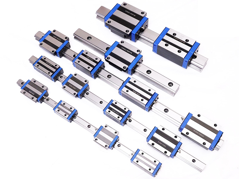
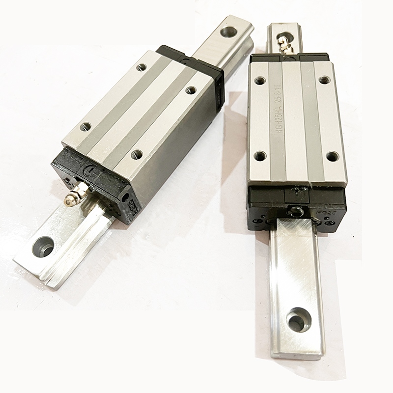
    【Linear guides】can be categorized into ball linear guides, roller linear guides, and wheel linear guides. They are used to support and guide moving parts, enabling them to perform reciprocating linear motion in a given direction. Based on the nature of friction, linear motion guides can be classified into sliding friction guides, rolling friction guides, elastic friction guides, and fluid friction guides.   1. Definition: Linear guides, also known as linear rails, slide rails, or linear guides, are used in linear reciprocating motion applications and can withstand a certain amount of torque, achieving high-precision linear motion under high loads.   
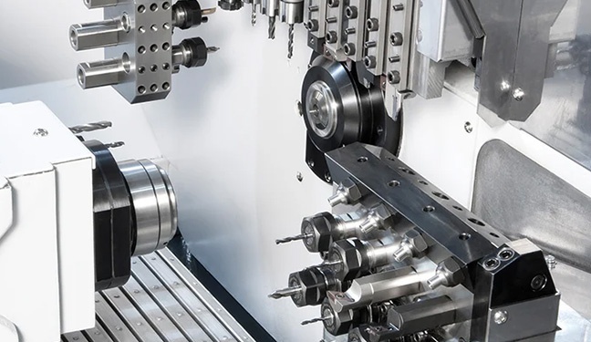
2. Function: The function of linear guides is to support and guide moving parts, enabling them to perform reciprocating linear motion in a given direction. Linear bearings are mainly used in automated machinery, such as German-imported machine tools, bending machines, and laser welding machines. Of course, linear bearings and linear shafts are used in conjunction. Linear guides are mainly used in mechanical structures with high precision requirements. The moving and stationary elements of a linear guide do not require an intermediate medium; instead, rolling steel balls are used.   
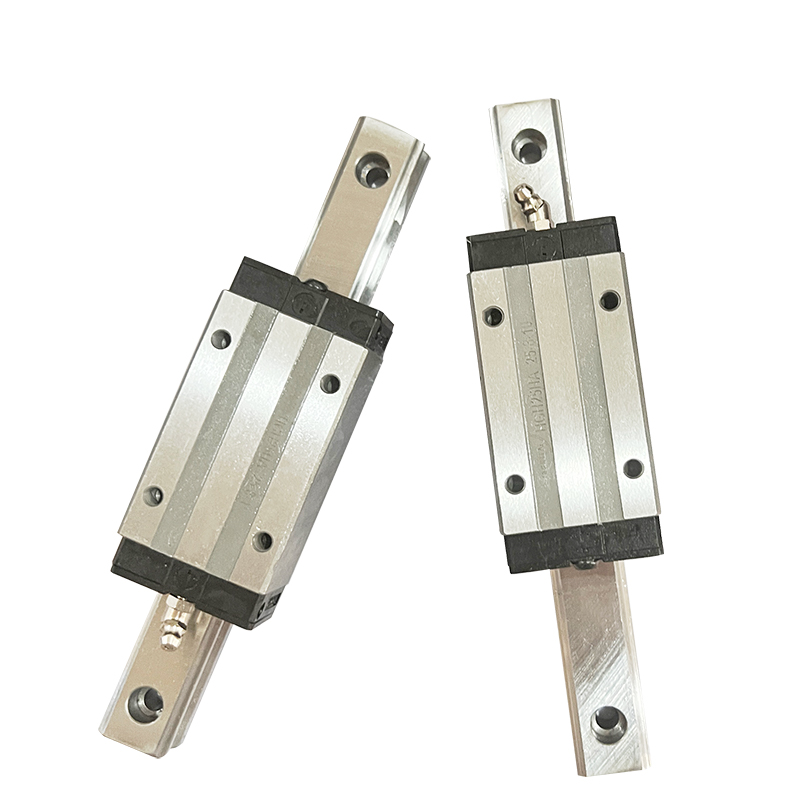
3. Working Principle: It can be understood as a rolling guide, where steel balls endlessly roll and circulate between the slider and the guide rail, allowing the load platform to move easily and linearly along the guide rail with high precision. This reduces the coefficient of friction to one-fiftieth of that of traditional sliding guides, easily achieving very high positioning accuracy. The end-unit design between the slider and the guide rail allows the linear guide rail to simultaneously bear loads in all directions (up, down, left, and right). The patented recirculation system and simplified structural design make HIWIN's linear guide rails have smoother and lower noise movement. The slider transforms the motion from a curve to a straight line. Like planar guide rails, linear guide rails have two basic components: a fixed component that acts as a guide, and a moving component. Since linear guide rails are standard components, for machine tool manufacturers, the only task is to machine a mounting plane and adjust the parallelism of the guide rail. The guide rail, acting as a guide, is made of hardened steel and is precision ground before being placed on the mounting plane. For example, a guide rail system that withstands both linear forces and overturning moments is significantly different in design from a guide rail that only withstands linear forces. Over time, the steel balls begin to wear, weakening the preload acting on them and reducing the motion accuracy of the machine tool's working parts. To maintain initial accuracy, the guide rail support, or even the guide rail itself, must be replaced. If the guide rail system already has a preload, and system accuracy has been lost, the only solution is to replace the rolling elements. The guide rail system is designed to maximize the contact area between the fixed and moving elements. This not only improves the system's load-bearing capacity but also allows it to withstand the impact forces generated by intermittent or heavy cutting, widely distributing the force and expanding the load-bearing area. To achieve this, guide rail systems use various groove shapes, with two representative types: Gothic (pointed arch) grooves, which are extensions of a semicircle with the contact point at the apex; and arc-shaped grooves, which serve the same purpose. Regardless of the structural form, the goal is the same: to maximize the contact radius of the rolling steel balls with the guide rail (fixed element). The key factor determining the system's performance characteristics is how the rolling elements contact the guide rail.   4. Application Areas: ① Linear guides are mainly used in automated machinery, such as German-imported machine tools, bending machines, laser welding machines, etc. Linear guides and linear shafts are used in conjunction. ② Linear guides are primarily used in mechanical structures with high precision requirements. The moving and fixed components of a linear guide do not use an intermediate medium but rather rolling steel balls. This is because rolling steel balls are suitable for high-speed motion, have a low coefficient of friction, and high sensitivity, meeting the working requirements of moving parts, such as tool holders and slides in machine tools. If the force acting on the steel balls is too large, or the preload time is too long, it will increase the resistance of the support movement.   5. Precautions for Use: Prevent Rusting: When handling linear guides directly by hand, thoroughly wash away sweat and apply high-quality mineral oil before handling. Pay special attention to rust prevention during the rainy season and summer. Keep the Environment Clean: Keep the linear guides and their surrounding environment clean. Even tiny dust particles invisible to the naked eye entering the guides will increase wear, vibration, and noise. Installation requires careful attention. Linear guides must be installed with utmost care. Forceful impacts, direct hammering, and pressure transmission through rolling elements are strictly prohibited. Appropriate installation tools are essential. Use specialized tools whenever possible, avoiding the use of cloths or short-fiber materials.   6. Cleaning the Guides: As core components of the equipment, guides and linear shafts function as guides and supports. To ensure high machining accuracy, the guides and linear shafts must possess high guiding precision and good motion stability. During operation, the workpiece generates significant amounts of corrosive dust and fumes. Long-term accumulation of these dust and fumes on the guide and linear shaft surfaces significantly impacts machining accuracy and can form pitting, shortening the equipment's lifespan. To ensure stable machine operation and product quality, regular maintenance of the guides and linear shafts is crucial. Note: For cleaning guides, prepare a dry cotton cloth and lubricating oil. Engraving machine guides are divided into linear guides and roller guides. Cleaning the linear guide rail: First, move the laser head to the far right (or left) to locate the linear guide rail. Wipe it with a dry cotton cloth until it is shiny and dust-free. Add a small amount of lubricant (sewing machine oil is acceptable; do not use machine oil). Slowly move the laser head left and right a few times to distribute the lubricant evenly. Cleaning the roller guide rail: Move the crossbeam to the inside, open the end covers on both sides of the machine, locate the guide rail, and wipe the contact areas between the guide rail and the roller with a dry cotton cloth. Then move the crossbeam and clean the remaining areas.   
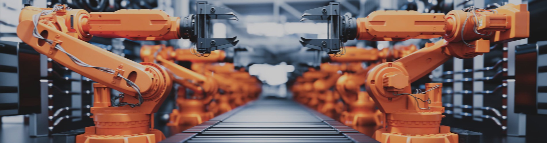
7. Development Prospects: With the continuous expansion of industries such as power, data communication, urban rail transit, automobiles, and shipbuilding, the demand for linear guide rails will grow rapidly. The linear guide rail industry has huge development potential in the future.   
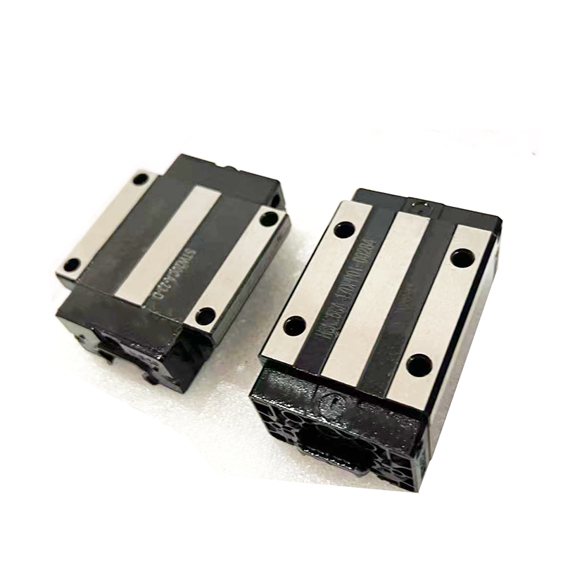
【Slide Block】The slide block material itself has appropriate hardness and wear resistance, sufficient to withstand the friction of movement. The hardness of the cavity or core part on the slide block should be the same level as other parts of the mold cavity and core. 1. Industrial Process Equipment: Molds are crucial process equipment for producing various industrial products. With the rapid development of the plastics industry and the widespread application of plastic products in aerospace, electronics, machinery, shipbuilding, and automotive industries, the requirements for molds are becoming increasingly stringent. Traditional mold design methods are no longer adequate. Compared to traditional mold design, Computer-Aided Engineering (CAE) technology offers significant advantages in improving productivity, ensuring product quality, reducing costs, and alleviating labor intensity.   2. Applications: Widely used in spraying equipment, CNC machine tools, machining centers, electronics, automated machinery, textile machinery, automotive, medical devices, printing machinery, packaging machinery, woodworking machinery, mold making, and many other fields.   If you have any questions in this regard, our product experts are happy to answer them! Our engineering team will be happy to answer your technical questions about the applications of our products as soon as possible. This article was compiled from online sources for the purpose of disseminating more information. If it infringes upon your rights, please contact us for deletion. For information on lead screws/guide rails/slider/spindles/machine tools, please feel free to contact us.
  • How to use linear guides efficiently? Dec 23, 2025
    The linear guide slider achieves efficient continuous operation 24 hours a day without jamming. The core reason lies in the synergistic effect of its structural design, lubrication system, and material manufacturing process, while the accompanying installation and maintenance specifications also play a crucial role. Specifically, this can be divided into the following aspects: High-precision rolling friction structure, replacing sliding friction The core of the linear guide is the rolling contact between the balls/rollers inside the slider and the guide rail. Compared to the surface contact of traditional sliding guides, the coefficient of friction in rolling contact is extremely low. This structure significantly reduces resistance and heat generation during operation. Even during long-term continuous operation, excessive frictional heat will not cause component expansion and jamming. Simultaneously, the circulating design of the balls/rollers ensures that the slider receives uniform force throughout its movement, without any jamming or interruption points. A stable and reliable lubrication system ensures long-term operation. Lubrication is a core element in preventing jamming. Linear guides are typically equipped with a long-lasting lubrication structure: The slider has a built-in oil reservoir and grease holder to store sufficient grease, continuously supplying oil to the ball/guide contact surfaces during operation, forming an oil film and reducing wear and resistance from direct metal-to-metal contact. Some industrial-grade guides also support automatic lubrication systems, which can replenish lubricant at regular intervals and in measured amounts to meet the lubrication needs of 24-hour uninterrupted operation. High-quality grease possesses high-temperature resistance, anti-aging properties, and load-bearing capacity, and will not be lost or fail due to temperature increases during prolonged operation. High-rigidity, wear-resistant materials and surface treatment processes The core components of the guide rails and sliders are generally made of high-carbon chromium bearing steel. After quenching, the hardness can reach HRC58~62, possessing extremely strong wear resistance and fatigue resistance. They are not prone to wear or deformation during long-term operation, avoiding jamming caused by component deformation. The guide rail surface undergoes precision grinding, achieving a roughness of Ra0.1~0.2μm. Combined with high-precision grinding of the ball bearings, this ensures smooth movement. Some products also undergo chrome plating, nitriding, and other surface treatments to further enhance wear resistance and rust prevention, preventing jamming caused by corrosion. Sealed and dustproof design to isolate external impurities Impurities (such as dust and iron filings) entering the slider are a common cause of jamming. Therefore, linear guides are equipped with professional seals: Dustproof sealing rings are installed at both ends of the slider, and a scraper plate is also provided on the outside to remove dust and debris from the guide surface, preventing them from entering the ball circulation channel; In harsh working conditions, dust covers, bellows, and other accessories can be added to completely isolate external contaminants, ensuring the cleanliness of internal moving parts and maintaining long-term smooth operation. Proper installation and load matching In practical applications, correct installation accuracy and load selection are also prerequisites for 24-hour jam-free operation: During installation, ensure the parallelism and straightness of the guide rail to avoid uneven force on the slider, uneven wear, and jamming due to installation deviations; During selection, choose a guide rail of appropriate specifications according to the actual load to ensure that the load is within the rated range and prevent overload from causing ball deformation or jamming.
Contact Us
Add: Chenggong Village Committee, Lukou Town, Nanjing, Jiangsu, ChinaTechnology Park
Subscribe

Please Read On, Stay Posted, Subscribe, And We Welcome You To Tell Us What You Think

submit

Get Directions

YOUTUBE

Copyright @ 2024 Nanjing Chunxin Automation Equipment Co., Ltd., Limited. All Rights Reserved. Network Supported

Sitemap Blog Xml Privacy Policy

leave a message

leave a message
If you are interested in our products and want to know more details,please leave a message here,we will reply you as soon as we can.
submit

home

products

WhatsApp

Contact