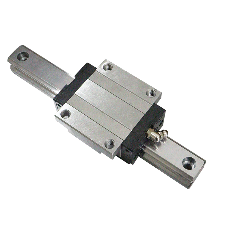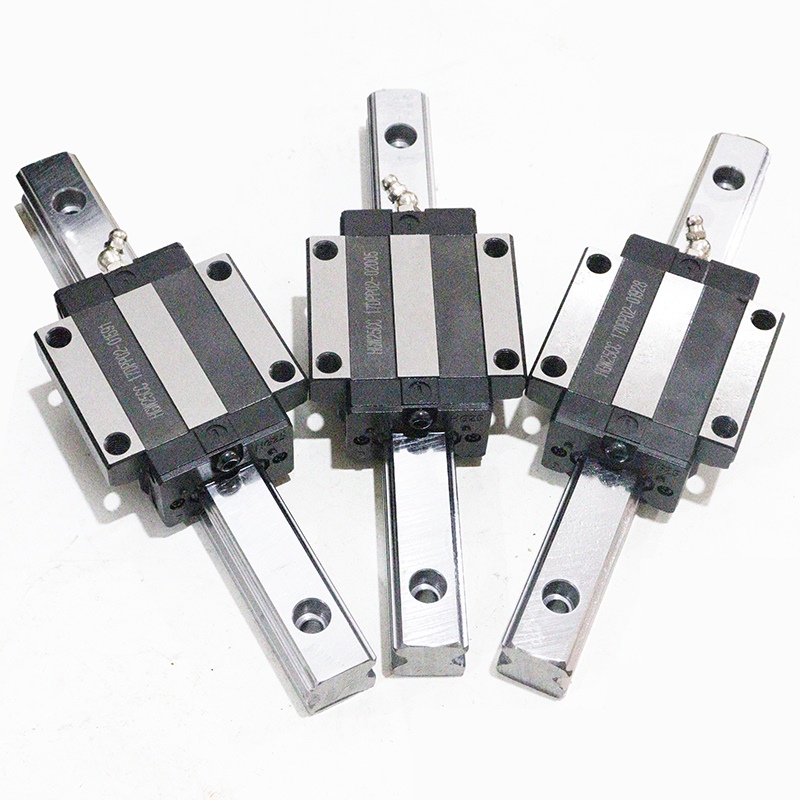


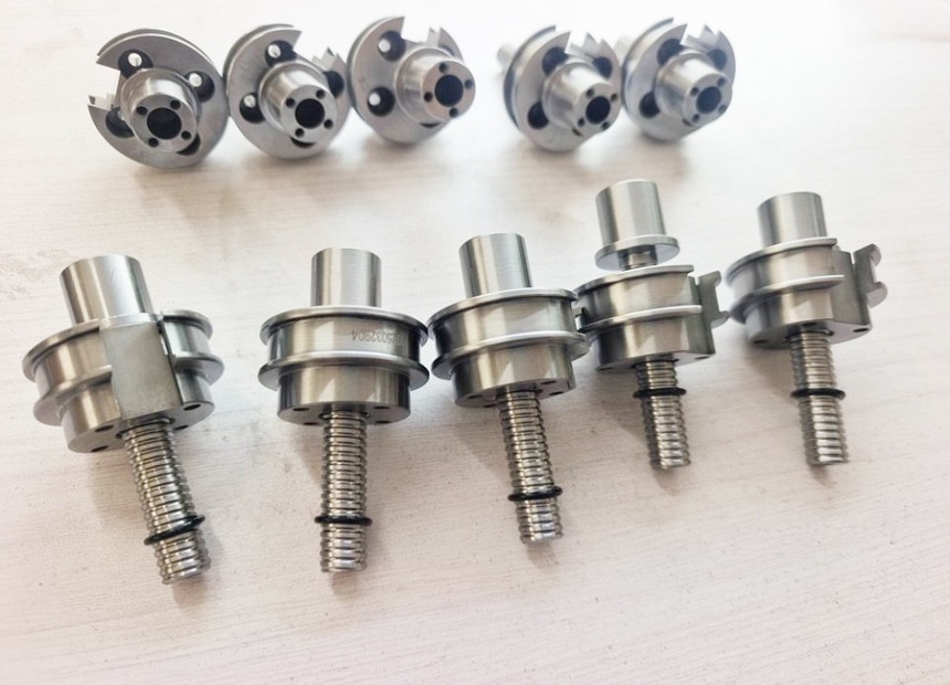


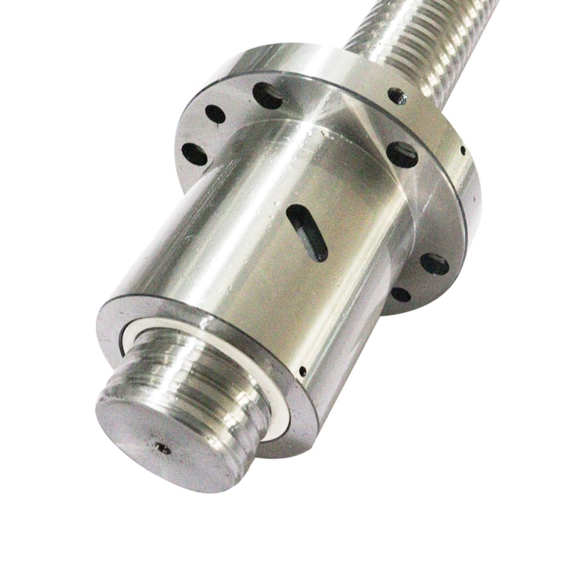
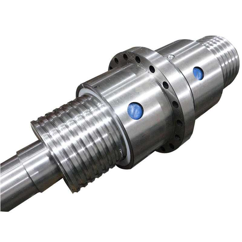
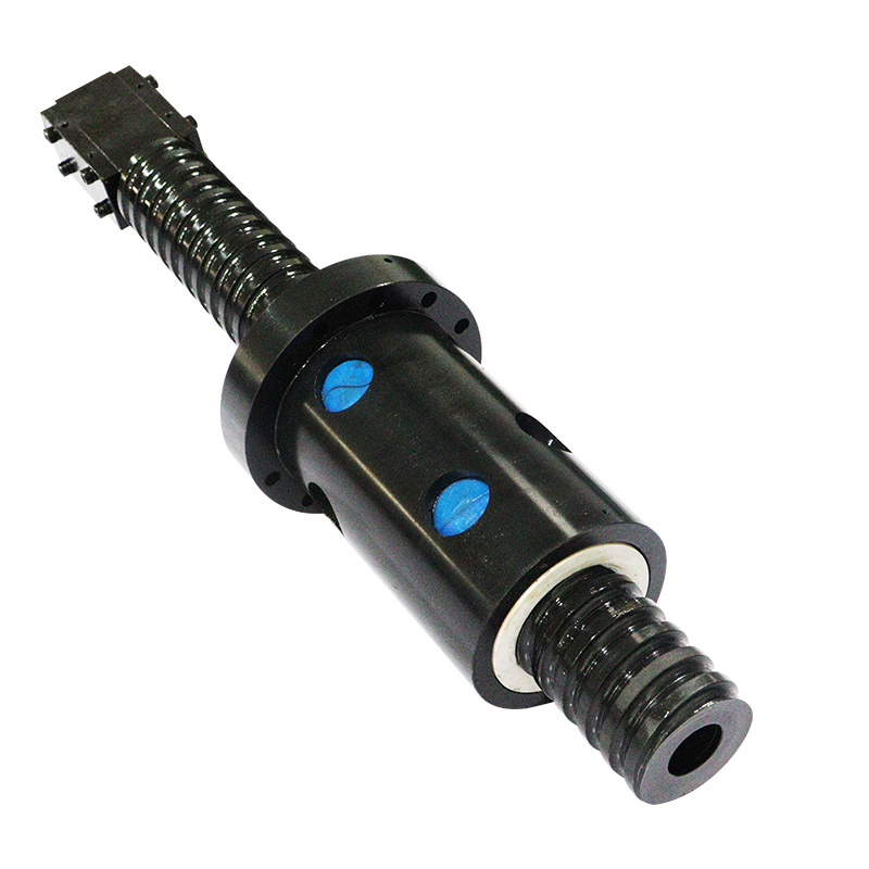
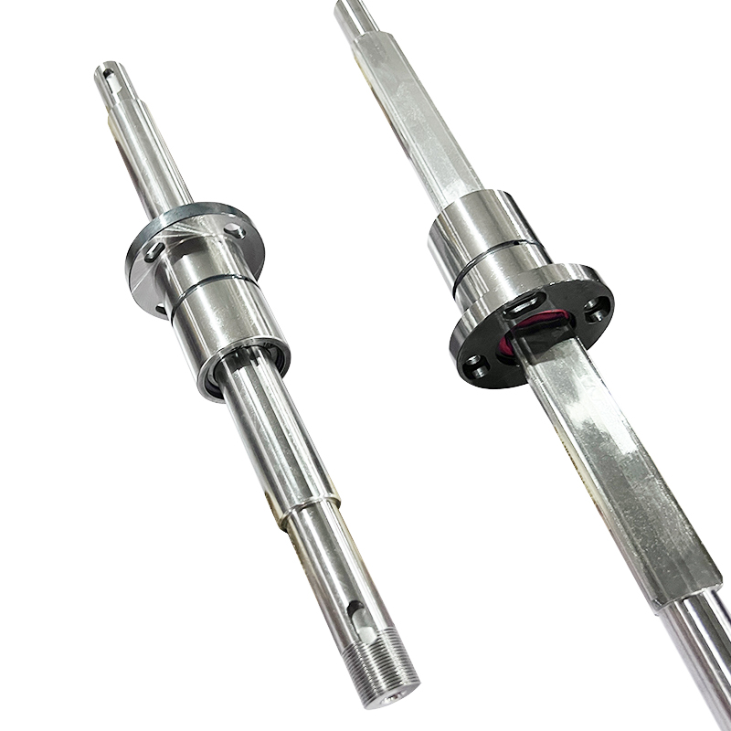
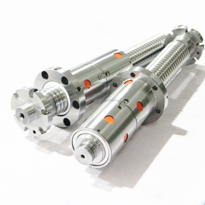
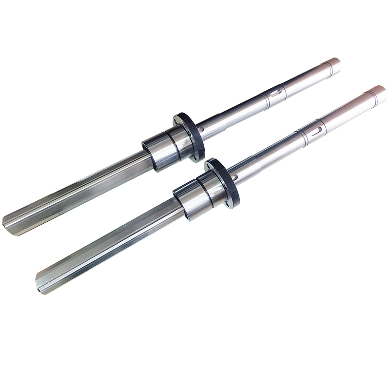
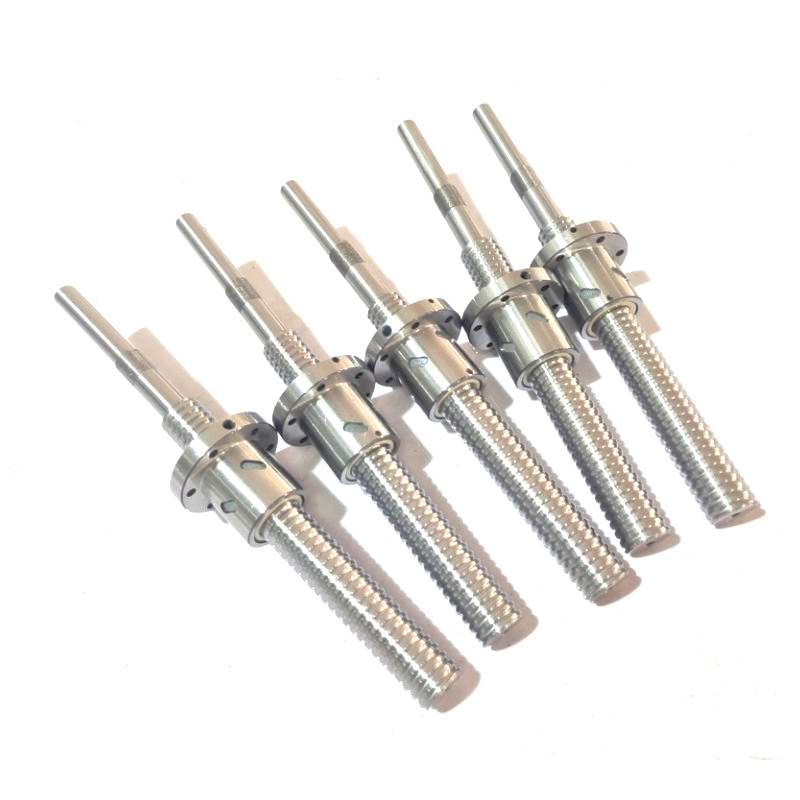
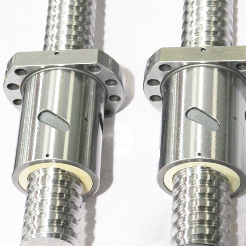
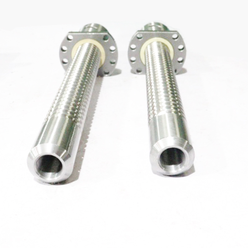
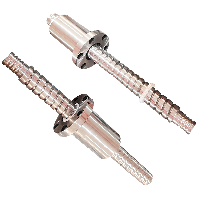
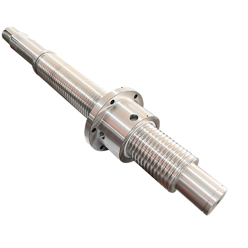
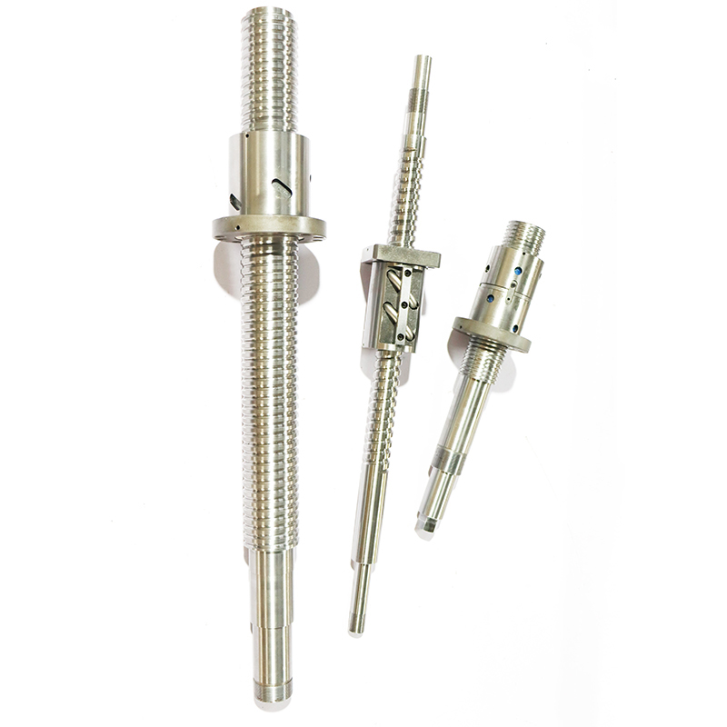
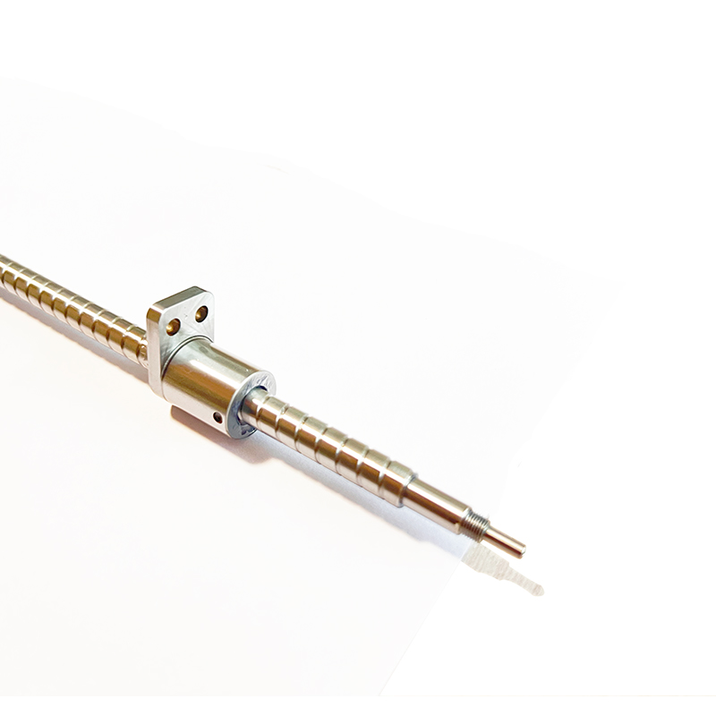
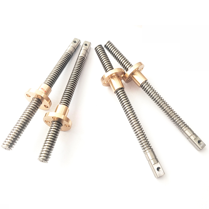
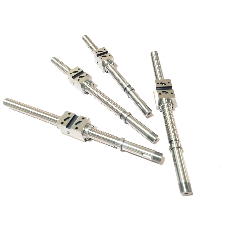
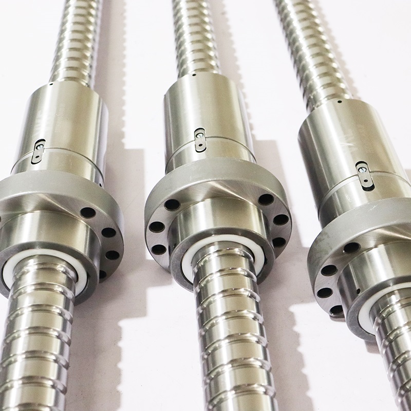
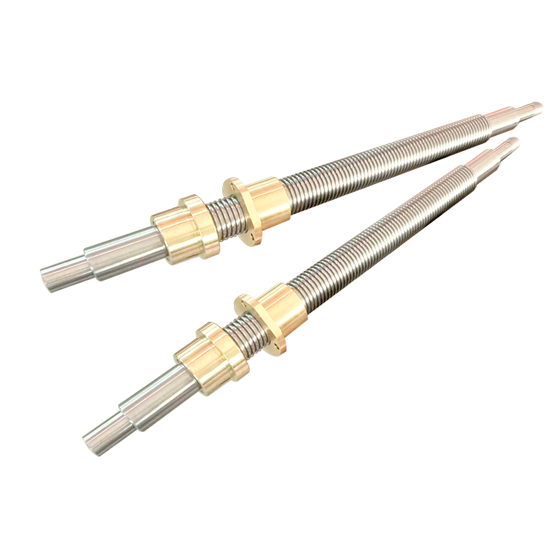
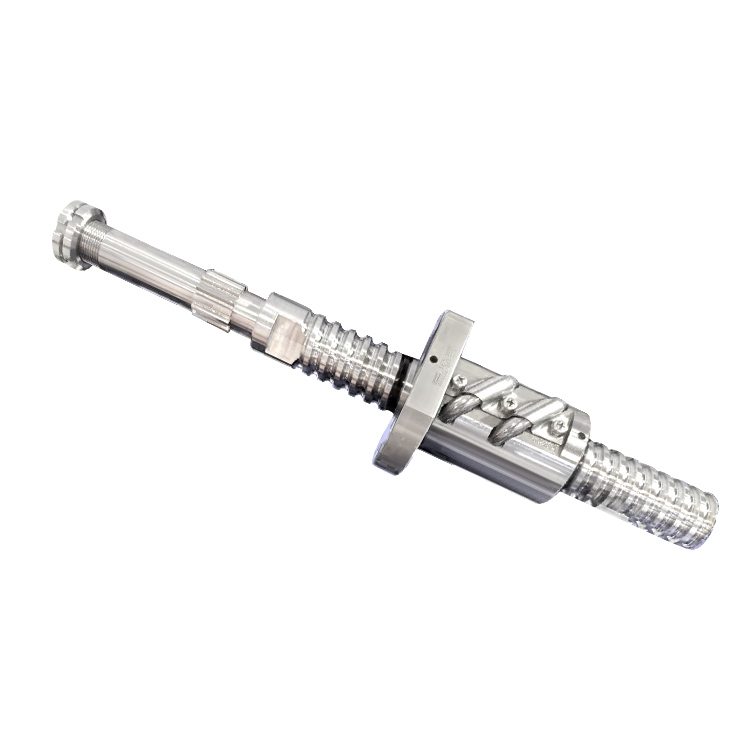
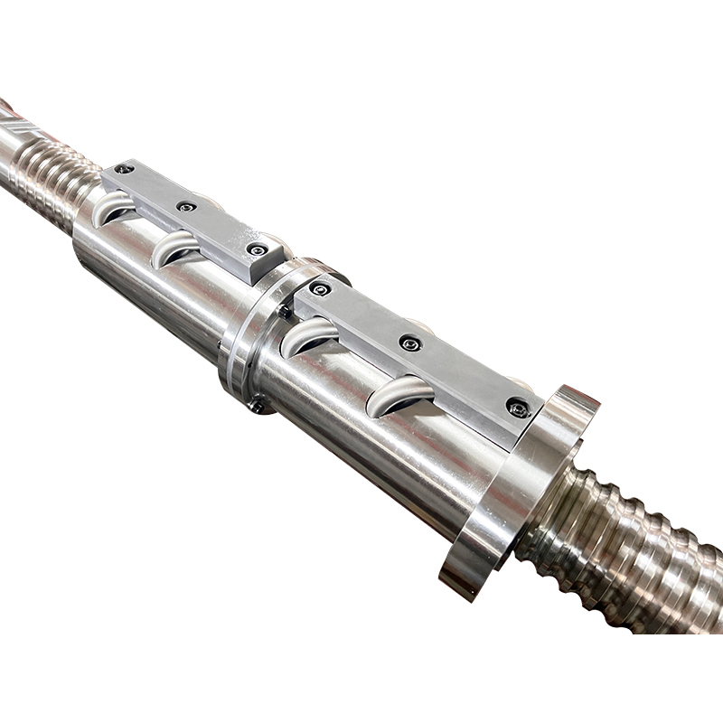
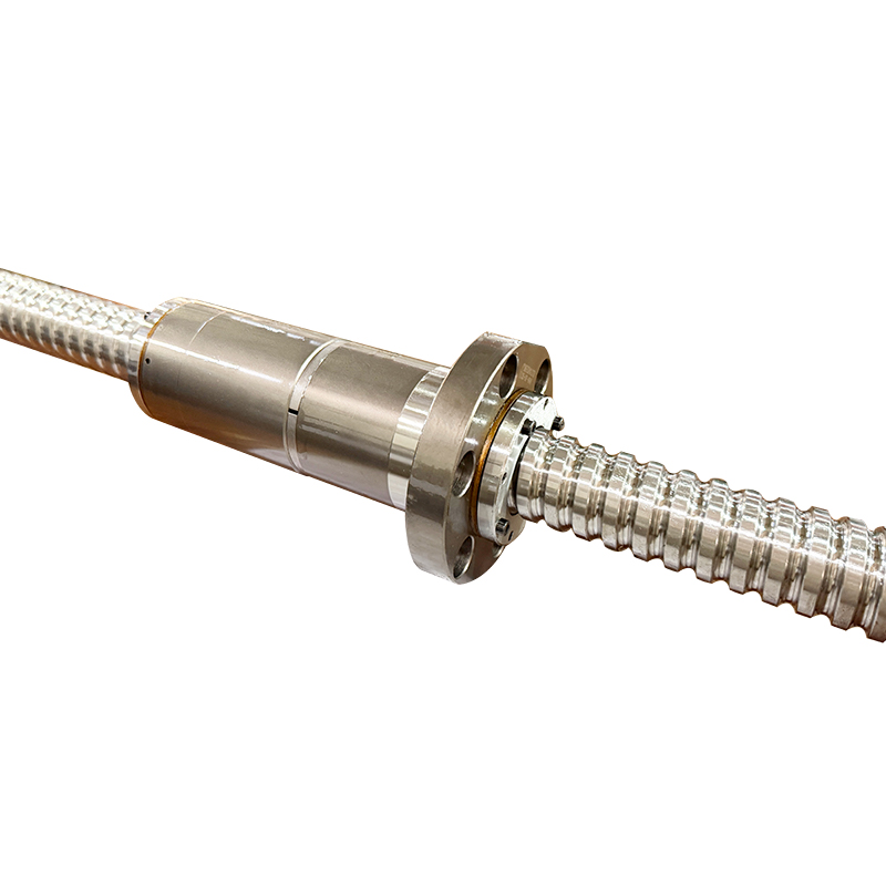
The ball screw/spline contains the ball screw grooves and the ball spline groove crossing one another. The nuts of the ball screw and the ball spline have dedicated support bearings directly embedded on the circumference of the nuts.The ball screw/spline is capable of performing three (rotational, linear, and spiral) modes of motion with a single shaft by rotating or stopping the spline nut.
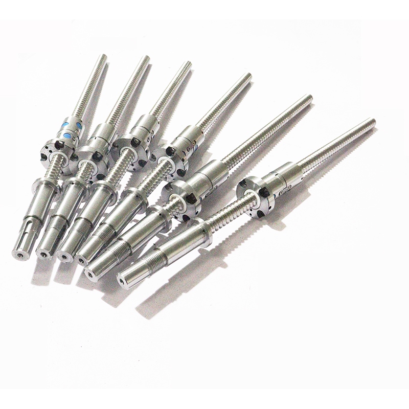
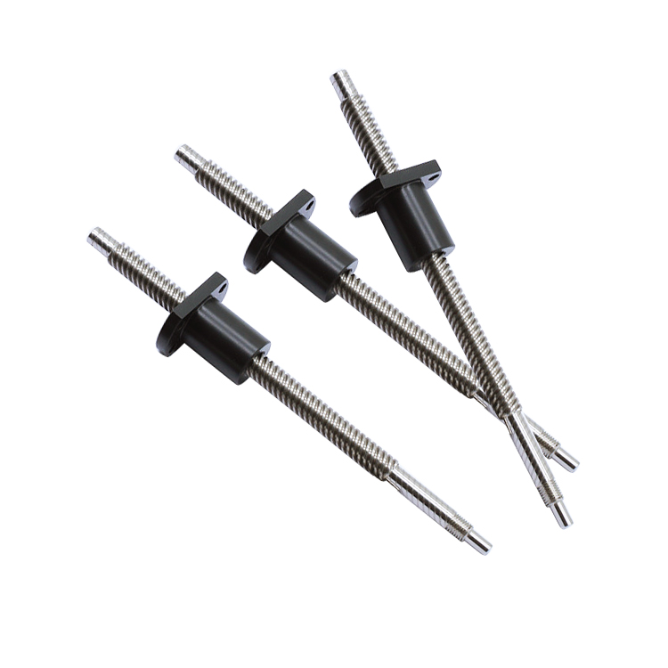
| Product Name | Miniature ball screw |
| Model Number | Customized according to drawings |
| Material | According to customer needs |
| Manufacturing Process | Rolled screw, Ground screw |
| Delivery | 14 days |
| Feature | High precision、High speed、Low noise、High efficiency |
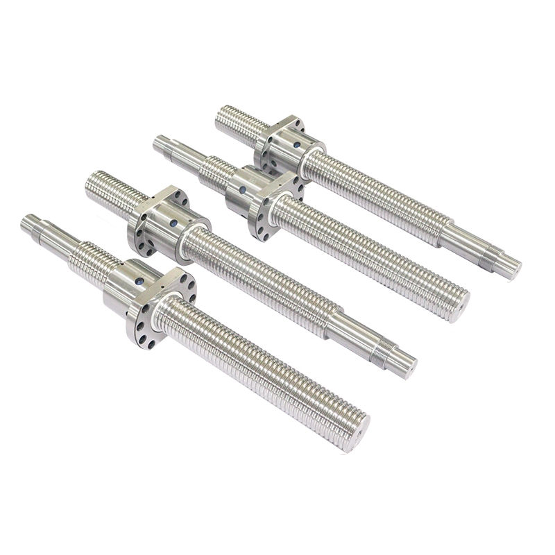
| Specification | Value |
| Diameter | 25 |
| Lead | 05 |
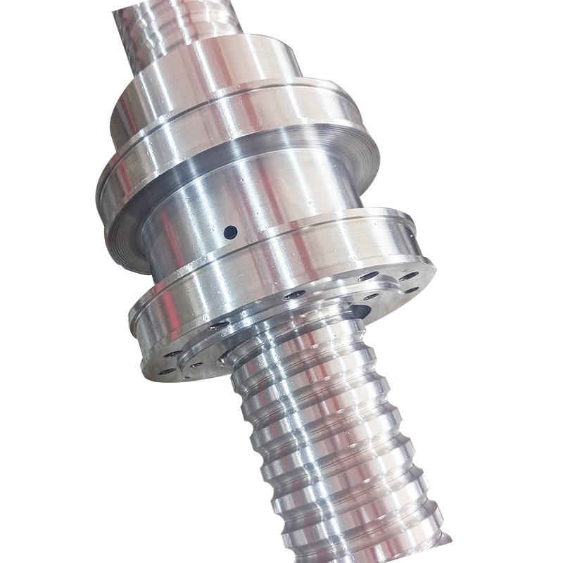
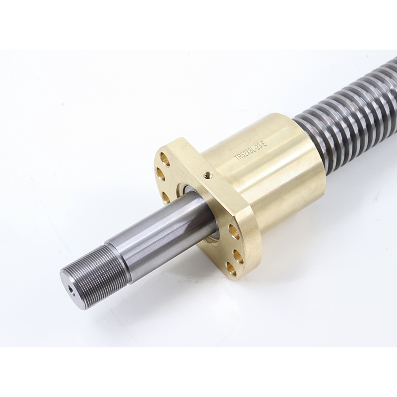
| Flange | Integral |
| Thread Direction | Right Hand |
| Lead Accuracy | C3 C5 |
| Advantage | High precision, high speed, long life, high reliability, low noise |
| Material | GCr15 Bearing steel |
| Packing | wooden box or according to customers' demands |
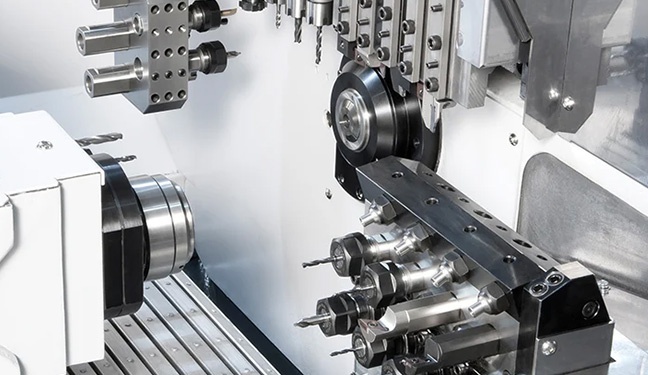
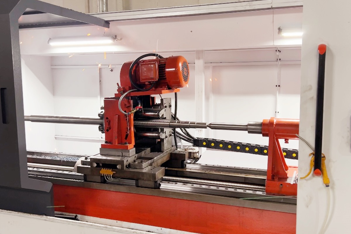
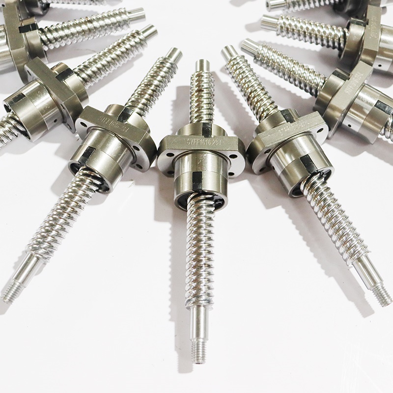
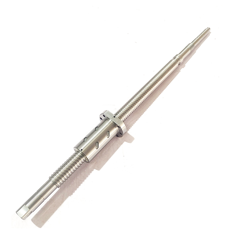
Ball screws are high-precision transmission components widely used in CNC machine tools, automated equipment, and other fields. Their machining steps must strictly adhere to precision control requirements, while paying attention to various process details. The following are the complete machining steps and precautions:
I. Ball Screw Machining Steps
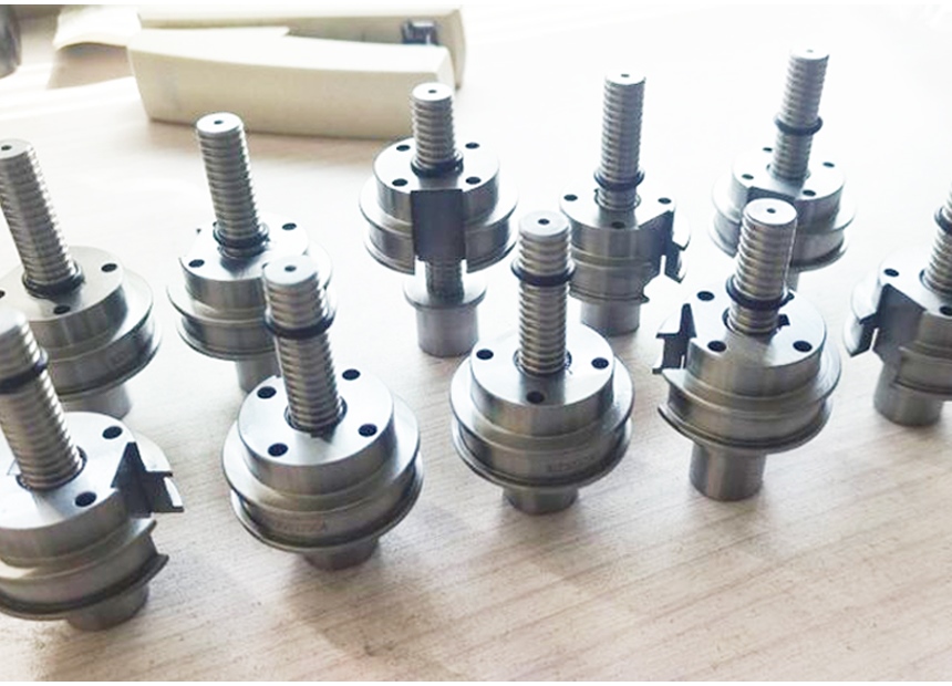
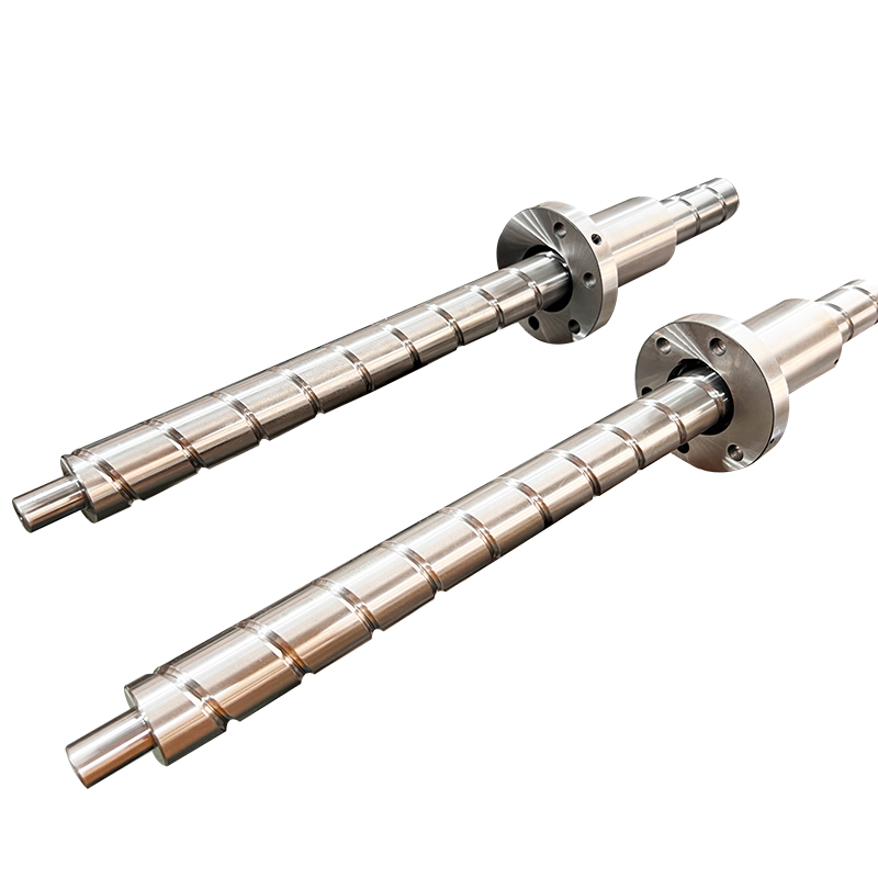
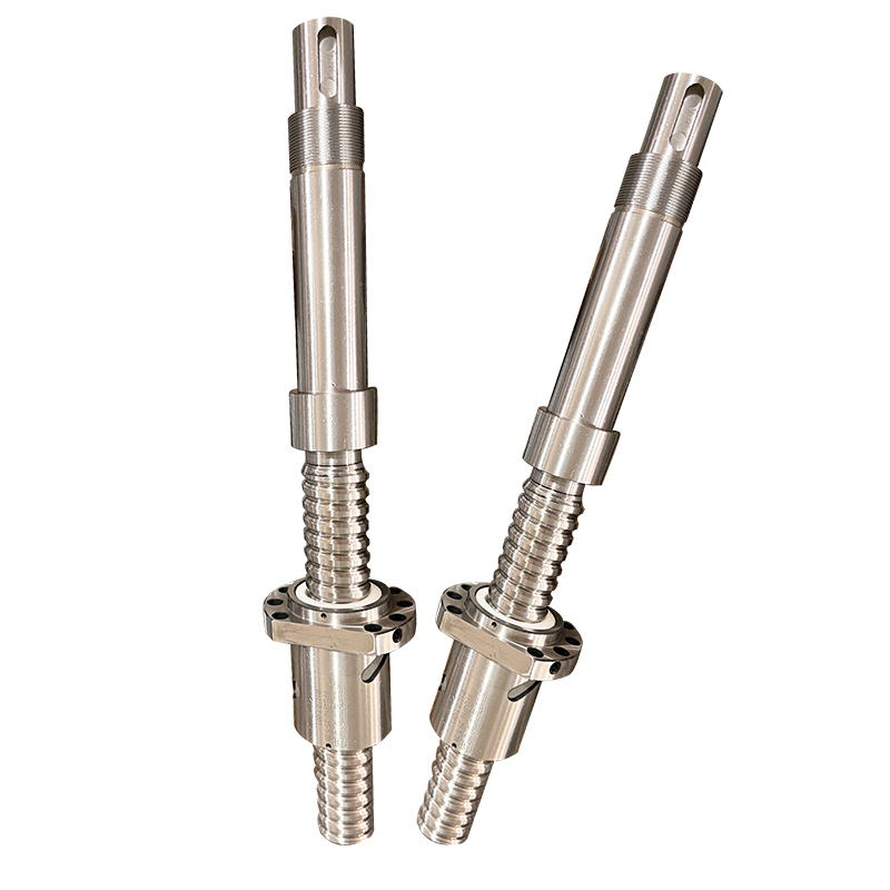
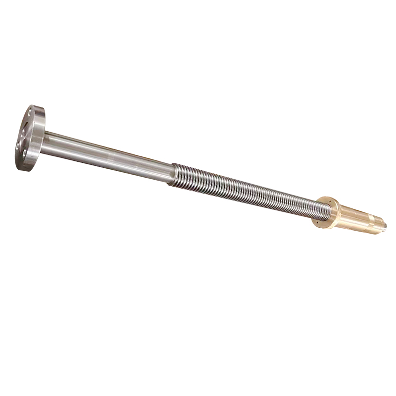
The core components of a ball screw include the screw shaft, balls, and nut. Machining the screw shaft is the core process, and the overall flow is as follows:
Raw Material Preparation and Blanking
Selecting suitable materials: High-carbon chromium bearing steel (such as GCr15) or alloy structural steel (such as 40Cr) is typically used. The material should possess high hardness, wear resistance, and good toughness.
Blanking: Based on the designed length of the screw, use a saw or cutting machine to cut the round steel into blanks, leaving a machining allowance (generally 3-5mm).
Rough Machining
Turning: Rough turning is performed on a conventional lathe or CNC lathe to machine the basic shape of the leadscrew, including the mounting journals at both ends, the pre-machined outer diameter for threading, and the relief groove. Most of the excess material is removed, leaving a 0.5-1mm allowance for semi-finishing.
Tempering: The rough-machined blank is tempered (quenching + high-temperature tempering) to obtain a uniform sorbite structure with a hardness of 220-250HB, improving the cutting performance and overall mechanical properties of the leadscrew.
Semi-finishing
Finish Turning: The outer diameter is finished on a CNC lathe to ensure cylindricity and dimensional tolerances, laying the foundation for threading.
Milling End Faces and Drilling Center Holes: The end faces of the leadscrew are milled flat on a milling machine, and then center holes (Type A or B) are machined using a center drill. These serve as the positioning reference for subsequent grinding and threading. The accuracy of the center hole directly affects the coaxiality of the leadscrew.
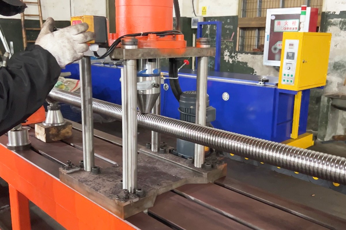
Thread Machining (Core Process)
Thread Rolling (Cold Rolling): For mass-produced ball screws, cold rolling is the preferred process. The semi-finished screw blank is pressed by a pair of thread rolling rollers on a thread rolling machine, causing plastic deformation of the metal to form threads. The advantages of cold-rolled threads are high efficiency, good thread surface quality, and high strength (grain flow lines are not interrupted).
Thread Turning (For Large Diameter or Non-Standard Screws): For small-batch, large-pitch or non-standard screws, threads are turned on a CNC lathe. After turning, a grinding allowance (0.1-0.2mm) must be left.
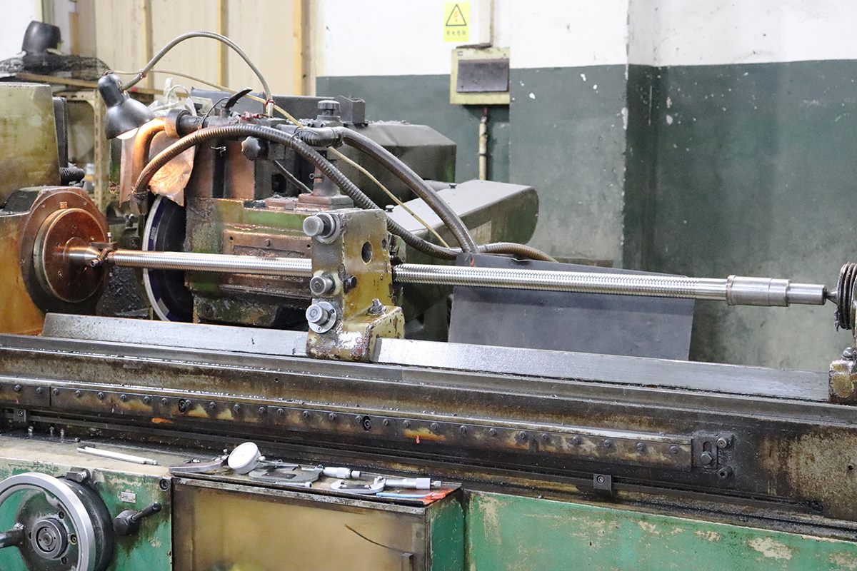
Thread Grinding (High Precision Requirements): For ball screws with a precision grade of C5 or higher, thread grinding is required. Using the center holes at both ends as positioning references, the thread profile, pitch, and outer diameter are ground to ensure thread accuracy and surface roughness (Ra≤0.4μm). Heat Treatment (Quenching + Tempering)
After thread machining, the lead screw shaft undergoes overall quenching (820-860℃, oil or water cooling), followed by low-temperature tempering (150-200℃) to achieve a surface hardness of HRC58-62, improving wear resistance and fatigue strength.
Note: Aging treatment is required after quenching to eliminate internal stress and prevent deformation during subsequent machining.
Fine Machining (Final Machining)
Precision Grinding of Outer Diameter and End Face: The mounting journal and end face of the lead screw are precision ground again on a grinding machine to ensure the roundness, cylindricity, and dimensional tolerances of the journal, meeting assembly requirements.
Thread Fine Grinding (Final Accuracy Calibration): For ultra-high precision lead screws, secondary thread grinding is required to correct deformation after heat treatment and ensure that pitch and thread profile errors are within design limits.
Chamfering and Deburring: Chamfering is performed on both ends of the lead screw and the thread edges to remove machining burrs and prevent scratching of the balls and nuts during assembly.
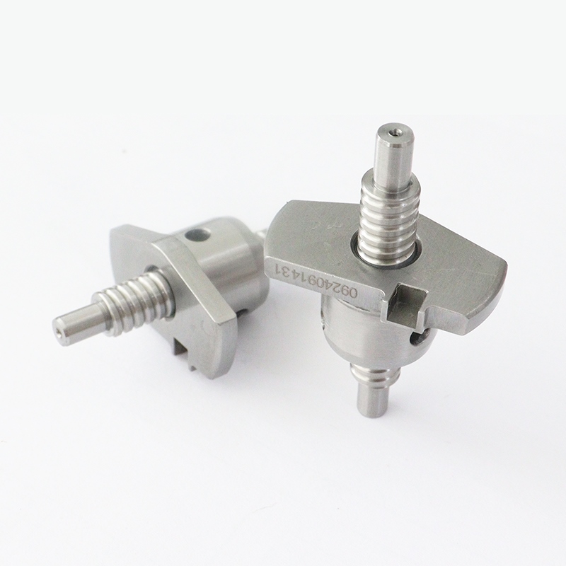
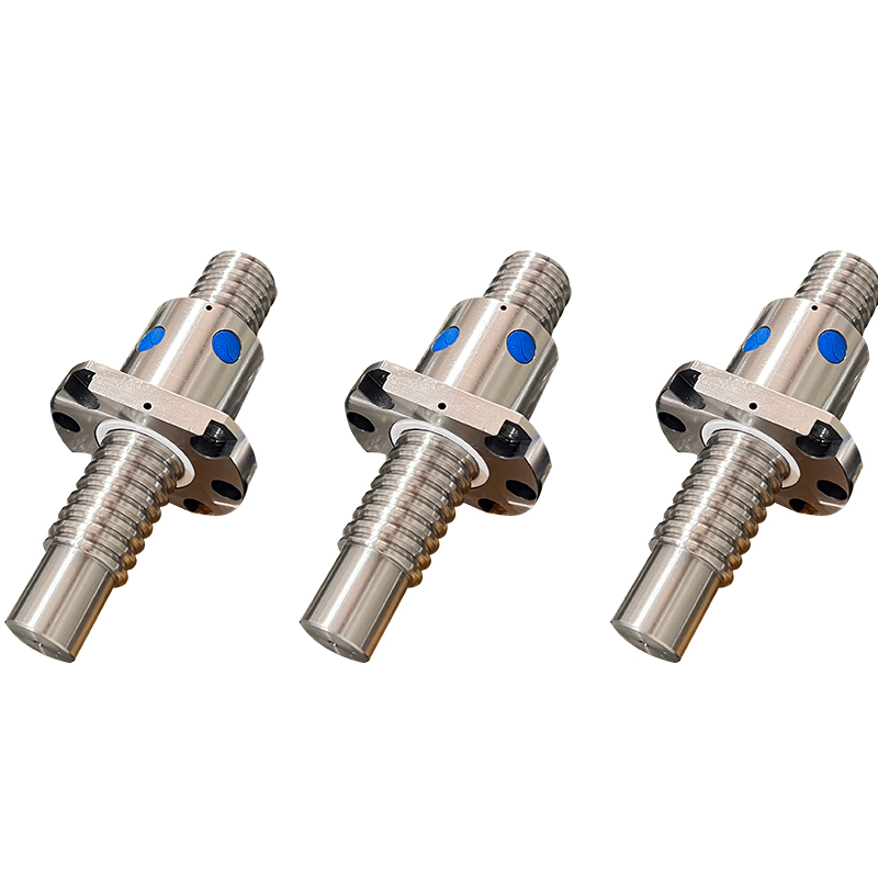
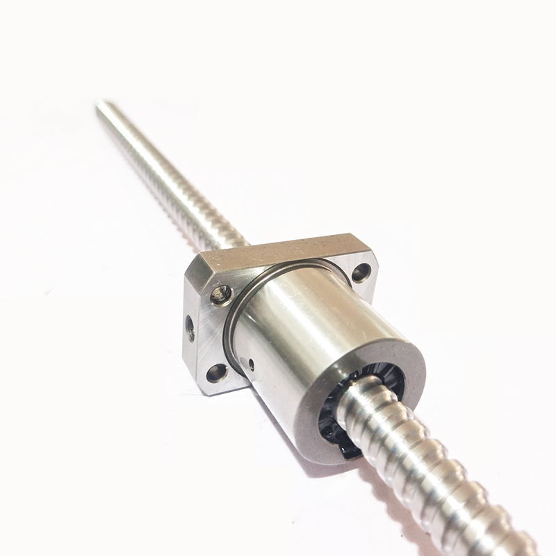
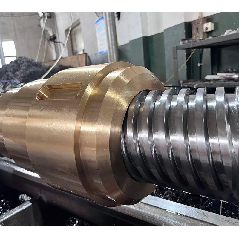
Nut Machining and Assembly
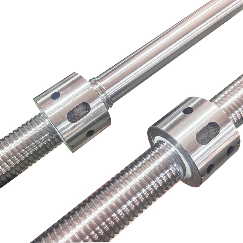
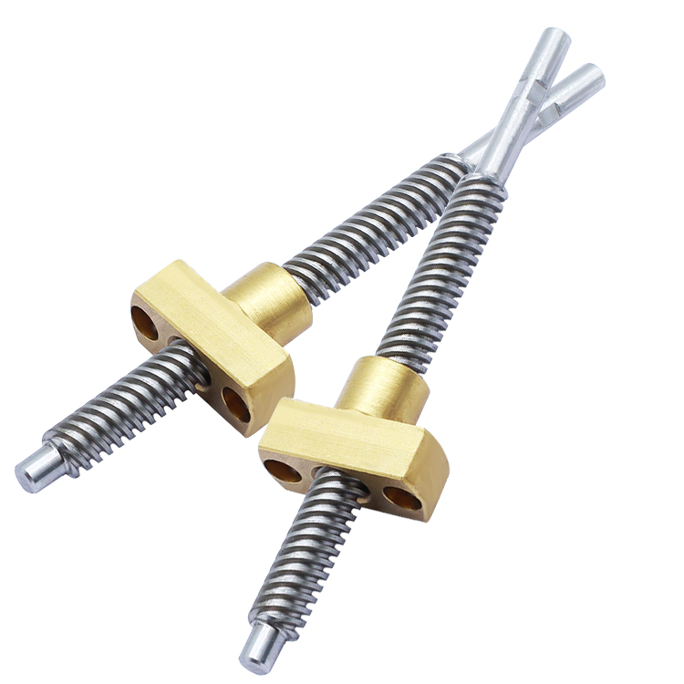
Nut Blank Machining: Nuts are typically made of bronze or engineering plastics. They are machined by turning, drilling, and tapping (or thread rolling) to create internal threads that match the lead screw. Simultaneously, ball circulation channels (such as guide holes for external circulation and reverser holes for internal circulation) are machined.
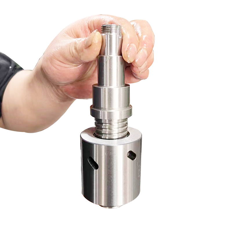
Ball Assembly: The balls are installed into the nut's circulation channels and the lead screw's thread raceways. A reverser or guide is installed to ensure smooth ball circulation. Pre-tightening is then performed (achieved by adjusting shim thickness or using a double-nut structure to eliminate backlash).
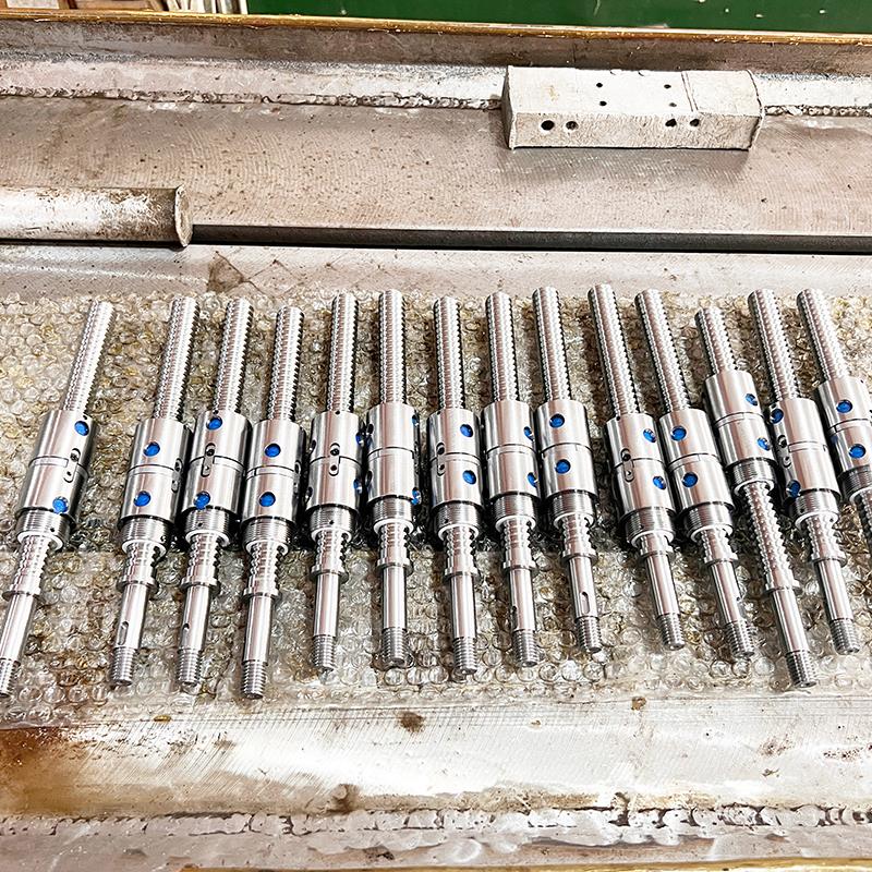
Inspection and Packaging
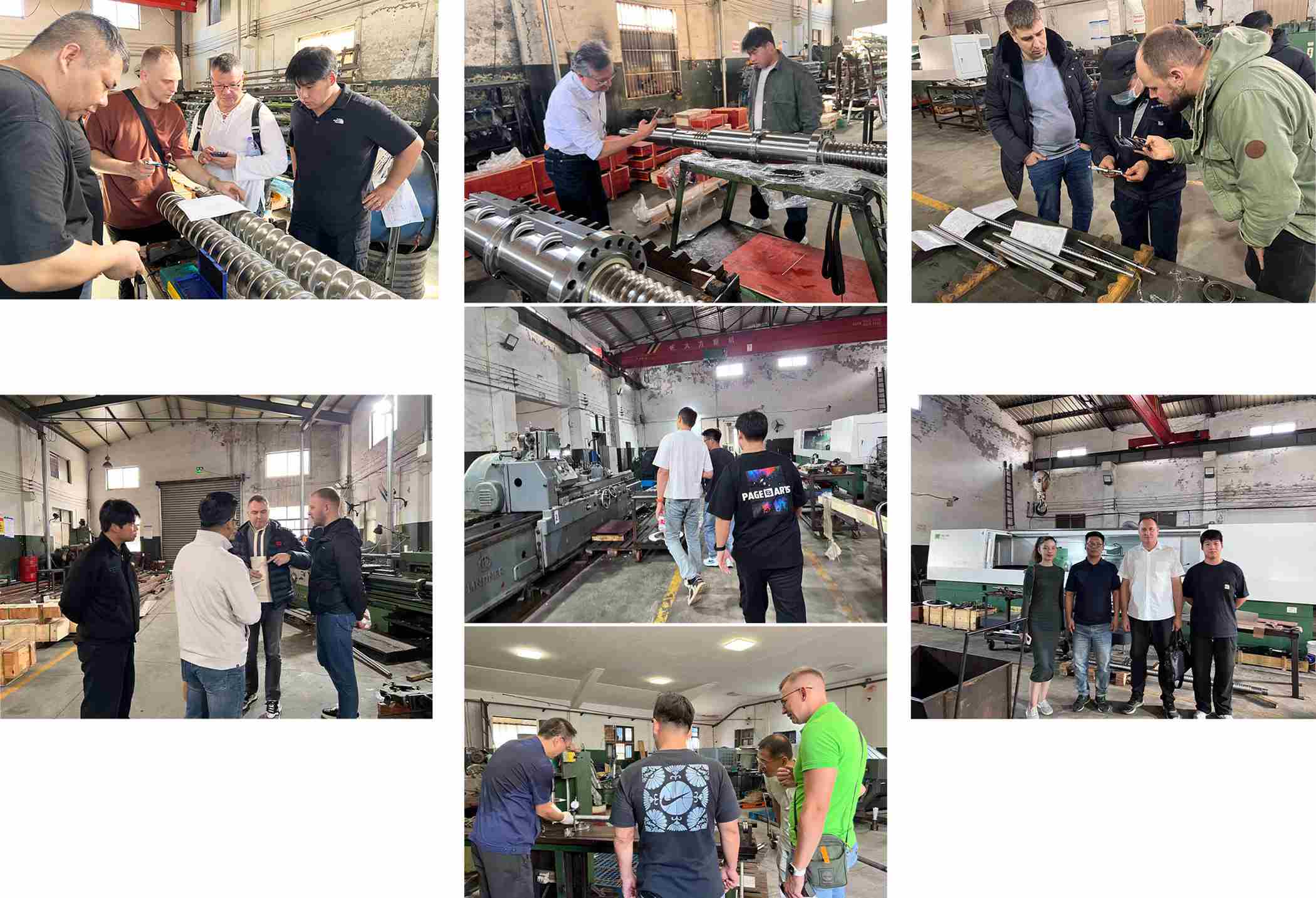
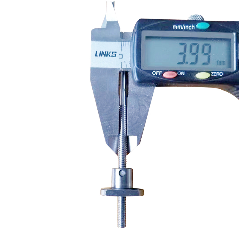
Accuracy Inspection: The lead screw's pitch error, thread angle, outer diameter tolerance, and surface roughness are inspected using a pitch meter, universal microscope, and surface roughness tester. The nut's preload and clearance are also checked.
Cleaning and Rust Prevention: After passing inspection, the cutting fluid and metal shavings on the lead screw and nut surfaces are cleaned, and rust-preventive oil is applied.
Packaging: The lead screw is wrapped in protective film to prevent damage to the threads during transportation.
II. Precautions During Machining
**Principle of Unified Datum**
The entire lead screw machining process must use the center holes at both ends as the positioning datum to avoid datum deviations caused by multiple clamping operations, ensuring the coaxiality and thread accuracy of the lead screw. The center holes need to be ground regularly to prevent wear from affecting positioning accuracy.
**Heat Treatment Deformation Control**
The lead screw must be preheated before quenching to avoid deformation caused by excessive temperature differences; after quenching, timely low-temperature tempering should be performed to eliminate internal stress; high-precision lead screws require multiple aging treatments to stabilize dimensions.
The lead screw after heat treatment needs to be checked for deformation. If the deformation exceeds the tolerance, it needs to be corrected by grinding.
**Thread Machining Accuracy Control**
When cold rolling threads, the accuracy of the thread rolling wheel and the rolling pressure must be strictly controlled. Excessive pressure will cause thread profile distortion, while insufficient pressure will result in incomplete thread filling.
During thread grinding, the grinding wheel speed, feed rate, and cooling effect of the grinding fluid must be controlled to prevent grinding burns (tempering color on the surface), which will affect the hardness and wear resistance of the lead screw. Surface Quality Protection
During machining, clean cutting fluid must be used to prevent metal shavings from adhering to the thread surface and causing scratches. Special grinding fluid should be used during grinding to cool, lubricate, and remove chips.
After machining, the lead screw must be handled with care to avoid impacts and scratches to the threads. Do not strike the lead screw directly with a hammer during assembly.
Dimensional and Geometric Tolerance Requirements
Strictly control the cumulative pitch error, thread profile half-angle error, and outer diameter cylindricity according to the accuracy grade specified in the design drawings (e.g., C3, C5, C7).
The clearance between the nut and the lead screw must be controlled within the design range. The preload must be uniform to avoid excessive tightness leading to excessive operating resistance, or excessive looseness resulting in loss of transmission accuracy.
Material Selection and Matching
The lead screw shaft must be made of a material with good hardenability to ensure uniform overall hardness. The nut material must match the lead screw material to avoid hard-on-hard contact that leads to excessive wear (e.g., bronze nuts with steel lead screws).


Please Read On, Stay Posted, Subscribe, And We Welcome You To Tell Us What You Think
Get Directions

Copyright @ 2024 Nanjing Chunxin Automation Equipment Co., Ltd., Limited. All Rights Reserved.
 Network Supported