How to resolve the problem of a ball screw failing to lock onto the bottom FK bearing?
Aug 01, 2025
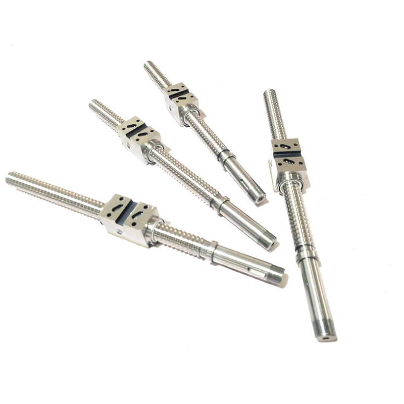
Machining a retaining ring groove at the end of the ball screw (i.e. installing a retaining ring/circlip) to replace the nut and locking ball screw fixing method is a feasible solution, but it requires comprehensive consideration of the design, process and application scenario adaptability. The following is a detailed analysis:
1. Feasibility of the Snap Ring Groove Solution
Advantages:
Simplified structure: Eliminating nuts and locking screws reduces the number of parts and assembly steps.
Loosening risk: Circlips are less likely to loosen under axial load (especially in low-vibration environments).
Space saving: Circlip grooves occupy less space, making them suitable for compact designs.
Limited axial load capacity: Circlips typically have lower axial load capacity than locknuts and may not be suitable for high-load or high-shock environments.
High installation accuracy requirements: The machining accuracy of the snap ring groove (such as groove depth, width, and roundness) directly affects the retaining effect of the snap ring.
Maintenance difficulties: Disassembly may require specialized tools, and repeated disassembly and assembly may cause wear in the snap ring groove.
2. Key Design Considerations
Snap Ring Groove Machining:
The groove dimensions must strictly match standard retaining ring specifications (such as DIN 471/472) to ensure that the retaining ring is fully seated and retains its elasticity.
The groove bottom must be smooth and burr-free to avoid stress concentration that may cause cracking.
CNC lathe machining is recommended to ensure the groove's perpendicularity to the axis and positional accuracy.
Axial retaining rings (such as DIN 472) are preferred. Their thickness and elasticity must be sufficient to withstand the axial force of the screw.
Adding a retaining ring washer may be considered to distribute the axial force and reduce wear on the groove.
Auxiliary fixing measures: Add thread sealant or anaerobic adhesive to the outside of the retaining ring groove to further enhance anti-loosening performance. Combined with end screwing (threaded holes machined into the screw end face and screwed against the bearing inner ring) provides a double fixation.
3. Implementation Recommendations
For light loads/low speeds: The retaining ring groove solution is feasible, but the retaining ring's condition requires regular inspection.
For heavy loads/high vibration: It is recommended to retain the lock nut or use a double nut + lock washer combination.
Verification testing: Simulate actual operating conditions (such as vibration and temperature rise) on a prototype to confirm whether the retaining ring exhibits axial movement.
4. Other Potential Improvements
Bearing Seat Design: Check the preload and fit tolerances of the FK bearings to ensure the bearings are free of play.
Screw Support: If space permits, a fixed-supported (rather than fixed-free) configuration can be used to reduce the risk of axial displacement.
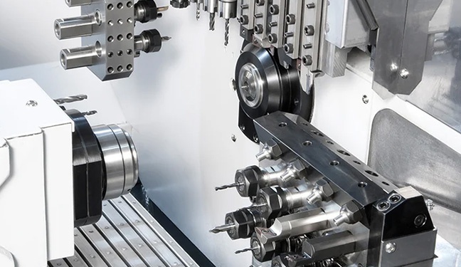
If a retaining ring groove solution is chosen, it is recommended to consult with the ball screw supplier to confirm the machinability of the end material (for example, whether the hardness allows for groove cutting) and to refer to similar application examples (such as the Z-axis mounting methods used on some small CNC machine tools).

 Network Supported